Library Exchange Format (LEF) File

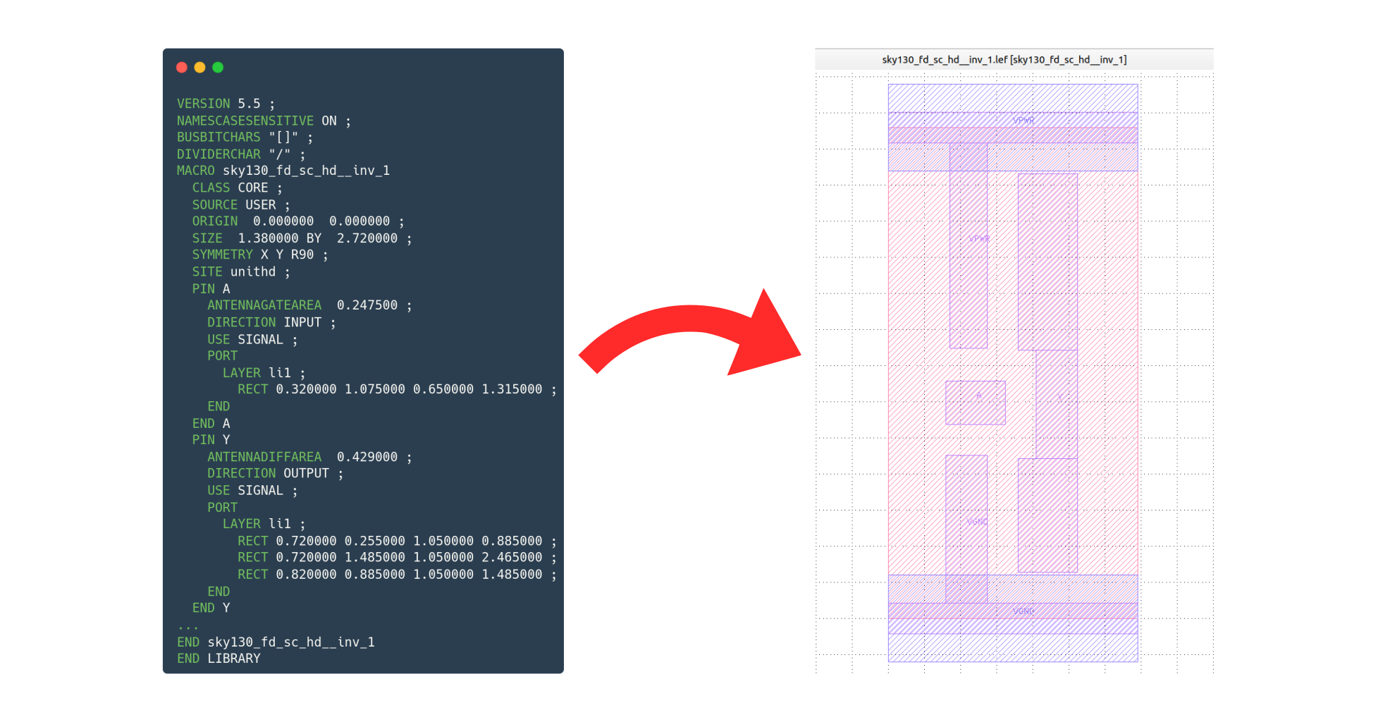
The Library Exchange Format (LEF) is an abstract representation of the layout written in ASCII, so it can be read in any text editor. A .lef file contains only the basic information essential for the purpose of the CAD tool in use. This simplified representation aims to optimize resource usage, such as memory, while the layout of a design is processed. The data in a LEF file includes definitions of layers, vias, placement site types and macros. In general, there are three main types of LEF files:
-
Tech LEF (.lef or .tlef): contains all the technology information, such as the rules for the metal layers, vias and placement sites available for the Process Design Kit (PDK) in use.
-
Cell LEF (.lef): contains all the abstracted physical information of the logic cells (std cells) of the PDK in use that can be placed in a circuit design.
-
Design LEF (.lef): the representation of a design that has already been physically synthesized. Similar to the cell LEF, but for a designed block.
Tech LEF
A Tech LEF file contains all the technology information for a design, such as placement and routing rules, and process information for the layers. The file can include the following statements:
[VERSION statement]
[BUSBITCHARS statement]
[DIVIDERCHAR statement]
[UNITS statement]
[MANUFACTURINGGRID statement]
[USEMINSPACING statement]
[CLEARANCEMEASURE statement]
[PROPERTYDEFINITIONS statement]

[LAYER (Nonrouting) statement
    | LAYER (Routing) statement]

[MAXVIASTACK statement]
[VIA statement]
[VIARULE statement]
[VIARULE GENERATE statement]
[NONDEFAULTRULE statement]
[SITE statement]
[BEGINEXT statement]
[END LIBRARY]
You can write the statements in any order. However, data must be defined before it is used. For example, the UNITS statement must be defined before any statement that uses values that depend on UNITS. For the Tech LEF example below we have:
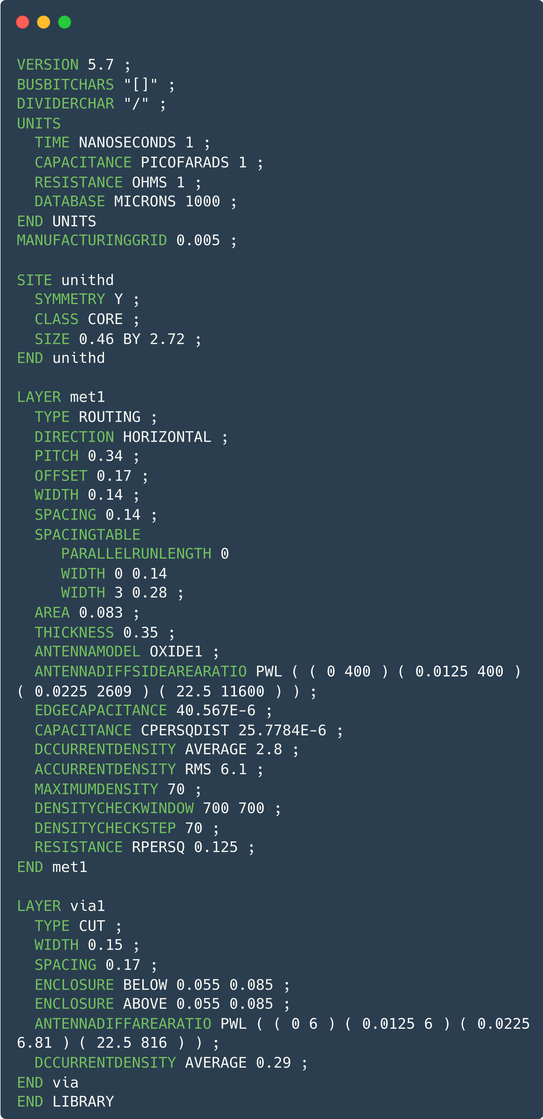 Example of a Tech LEF file
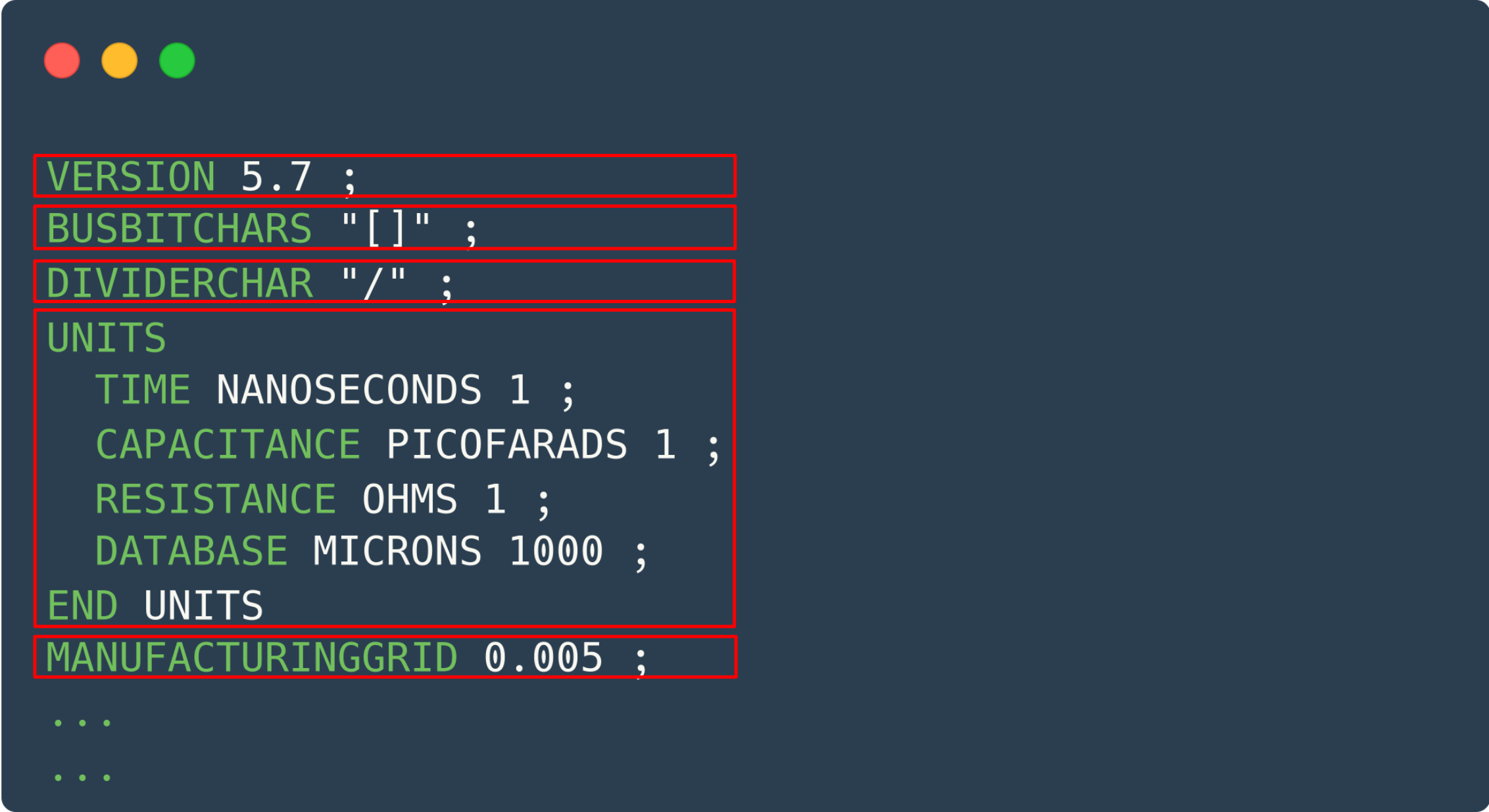 Header of a Tech LEF file
VERSION number: Specifies which version of the LEF syntax is being used. The number is a string in the major.minor[.subMinor] format, such as 5.6 or 5.7.
BUSBITCHARS “delimiterPair”: Specifies the pair of characters used to define bus bits when LEF names are mapped to or from other databases. The characters must be enclosed in double quotes. For example:
BUSBITCHARS ”[]”:
If one of the bus bit characters appears in the name of a LEF element as a regular character, you must put a backslash () before it so the LEF reader does not interpret it as a bus bit delimiter. If you do not specify the BUSBITCHARS statement in your LEF file, the default value is ”[]”.
DIVIDERCHAR “character”: Specifies the character used to express hierarchy when LEF names are mapped to or from other databases. The character must be enclosed in double quotes. For example:
DIVIDERCHAR ”/”:
If the divider character appears in the name of a LEF element as a regular character, you must put a backslash () before it so the LEF reader does not interpret it as a hierarchy delimiter. If you do not specify the DIVIDERCHAR statement in your LEF file, the default value is ”/”.
UNITS
    [TIME NANOSECONDS convertFactor ;]
    [CAPACITANCE PICOFARADS convertFactor ;]
    [RESISTANCE OHMS convertFactor ;]
    [POWER MILLIWATTS convertFactor ;]
    [CURRENT MILLIAMPS convertFactor ;]
    [VOLTAGE VOLTS convertFactor ;]
    [DATABASE MICRONS LEFconvertFactor ;]
    [FREQUENCY MEGAHERTZ convertFactor ;]
END UNITS
The UNITS statement defines the units of measurement in the LEF. The values tell how to interpret the numbers found throughout the file.
MANUFACTURINGGRID value: Defines the manufacturing grid for the design. The manufacturing grid is used to align geometries. When it is specified, shapes and cells are placed at locations that snap to the manufacturing grid.
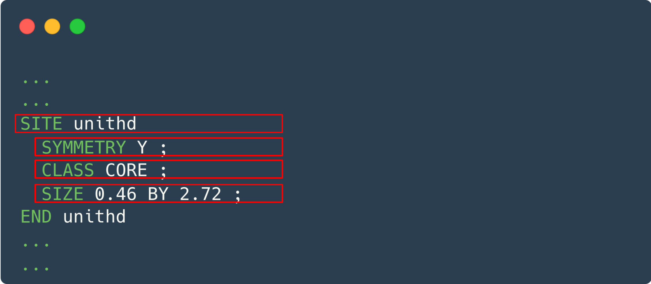 Site definition in a Tech LEF file
SITE siteName
    CLASS {PAD | CORE} ;
    [SYMMETRY {X | Y | R90} ... ;]
    [ROWPATTERN {previousSiteName siteOrient} ... ;]
    SIZE width BY height ;
END siteName
The SITE statement provides the minimum placement grid for a set of std cells, such as I/O, core, block, analog, digital, short, tall and so on. Every std cell must have a width and height that are multiples of the site size.
SYMMETRY {X | Y | R90}: Indicates which site orientations are equivalent. The sites in a given row have the same orientation as the row.
CLASS {PAD | CORE}: Specifies whether the site is an I/O pad site or a core site.
SIZE width BY height: Specifies the dimensions of the site in the normal (or north) orientation, in micrometers.
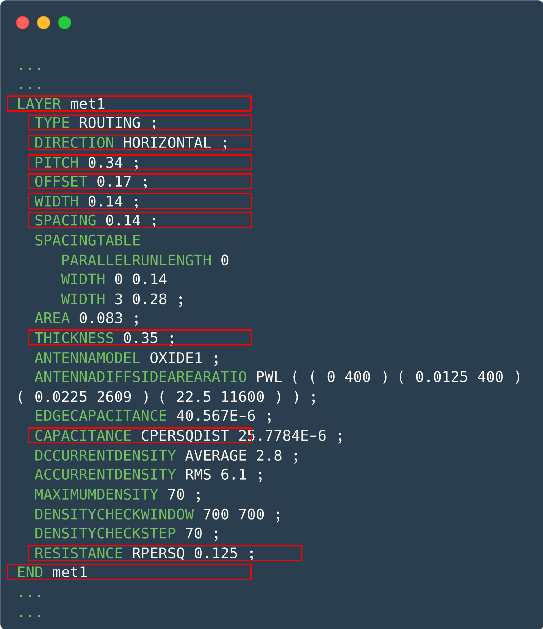 Metal layer definition in the Tech LEF
The LAYER statements define the routing layers available in the technology that can be used in the block being designed. Each layer is defined by giving it a name and design rules. Routing layers must be defined separately, each with its own attribute statements. You must define the layers in process order, from bottom to top. For example:
    poly    masterslice
    cut01   cut
    met1    routing
    cut12   cut
    met2    routing
LAYER layerName: Specifies the name of the layer. This name is used in later references to the layer.
DIRECTION {HORIZONTAL | VERTICAL | DIAG45 | DIAG135}: Specifies the preferred routing direction of the metal. Automatic routing tools try to route using the preferred direction of each layer.
PITCH {distance | xDistance yDistance}: Specifies the required routing distance between tracks of the same layer. The PITCH is used to generate the routing grid (the DEF tracks).
WIDTH distance: Specifies the wire width values, in micrometers. More than one wire width can be specified. If several width values are given, they must be listed in increasing order.
SPACING distance: Specifies the default minimum spacing, in micrometers, allowed between two geometries of different nets.
The spacing rules apply to pin-to-wire, obstruction-to-wire, via-to-wire and wire-to-wire spacing. These requirements specify the minimum spacing allowed by default between two geometries on different nets. The figure below shows some examples of the Tech LEF properties presented in this section.
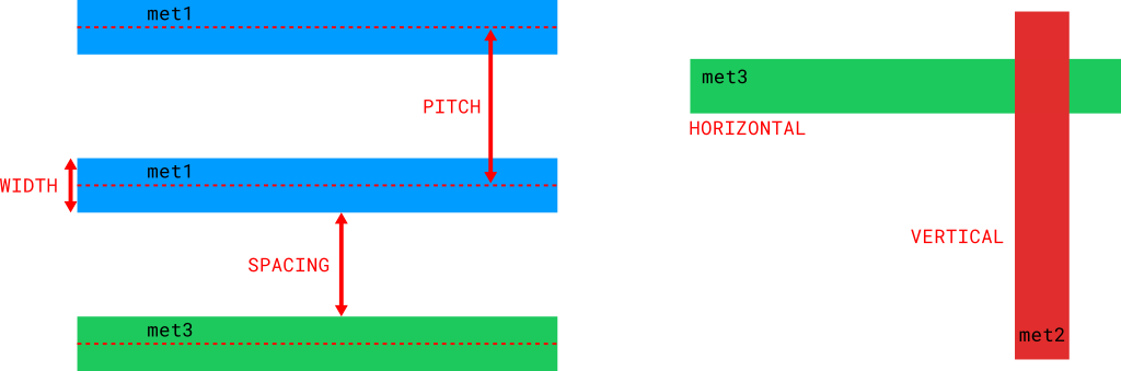 Example of the metal layer rules in the Tech LEF
To connect different metal layers we need a cut layer between the two metal layers being connected. These connections are called VIAs. A via can have a single connection point (single cut) or several connection points (multi cut) between the metal layers. The attributes of a via in the LEF are similar to those of the metals.
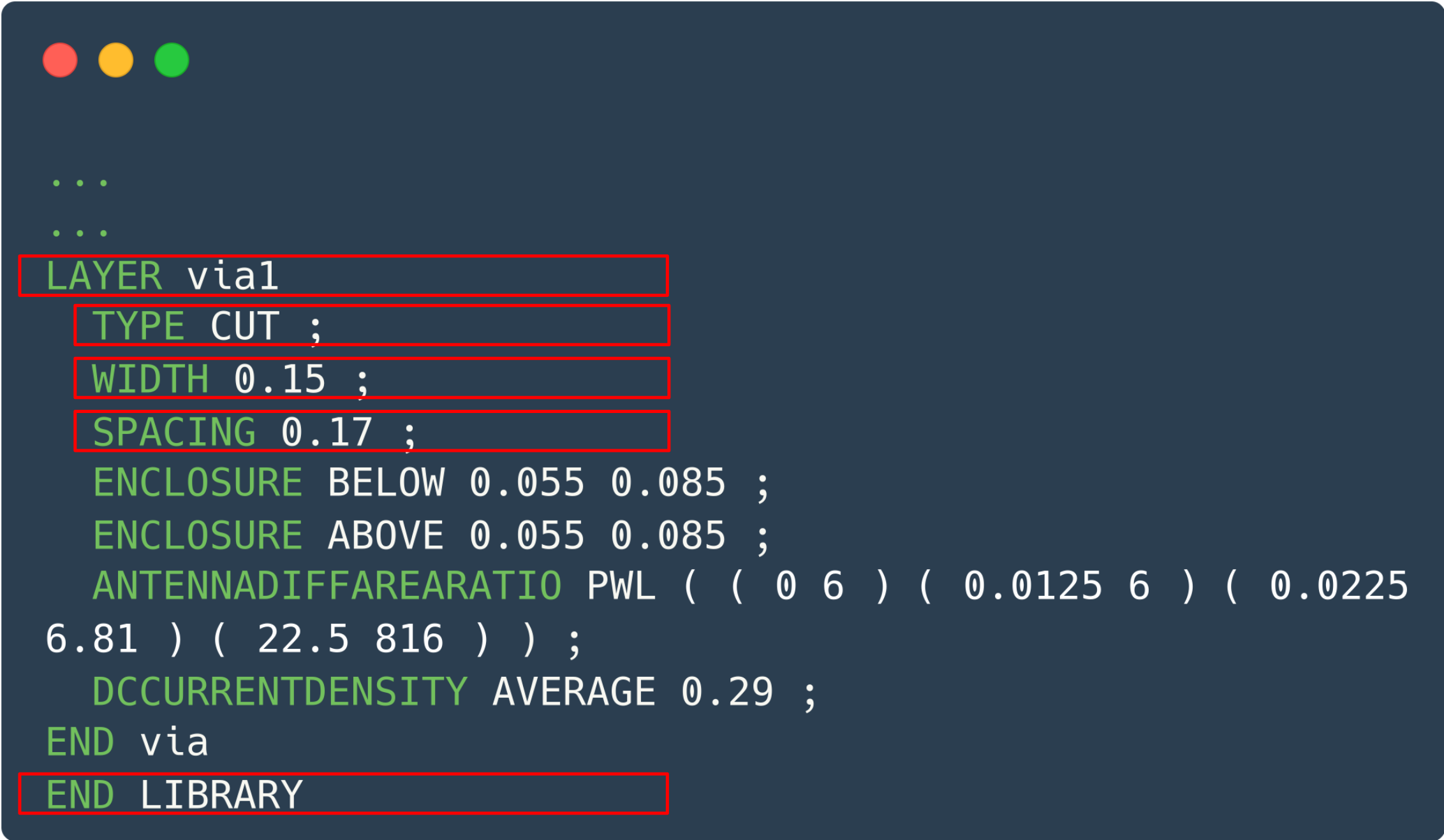 Example of the via rules in the Tech LEF
Every LEF file must end with the END LIBRARY statement.
Cell LEF
A cell library LEF file (std cell LEF) contains the information on the logic cells of a given Process Design Kit (PDK). A std cell LEF file can include the following statements:
[VERSION statement]
[BUSBITCHARS statement]
[DIVIDERCHAR statement]
[VIA statement]
[SITE statement]
[MACRO statement]
[PIN statement]
[OBS statement]
[BEGINEXT statement]
[END LIBRARY] 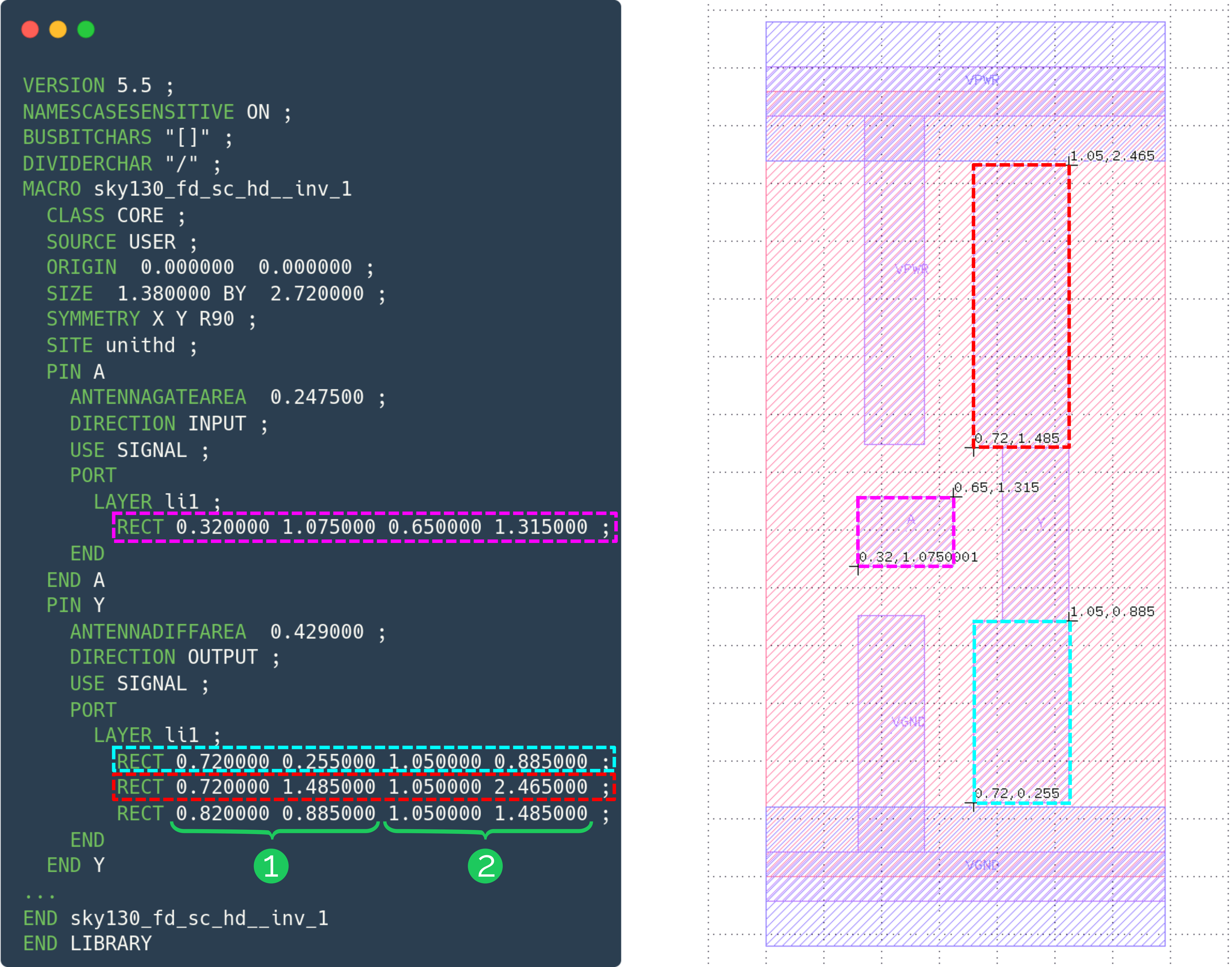 Example of a Macro LEF file
The statements in the cell LEF file represent the geometries that make up the layout of the std cells in the PDK library. Each rectangle in the file is associated with a metal LAYER and is defined by a set of two points with xy coordinates. These two points are the diagonally opposite corners of the geometry: the first pair of coordinates is the lower-left point and the second pair is the upper-right point.
Design LEF
The Design LEF file is an abstract representation of a design that has already been physically synthesized. This LEF is similar to the cell LEF, but applied to a designed block. In this case, the whole block is treated as a macro.
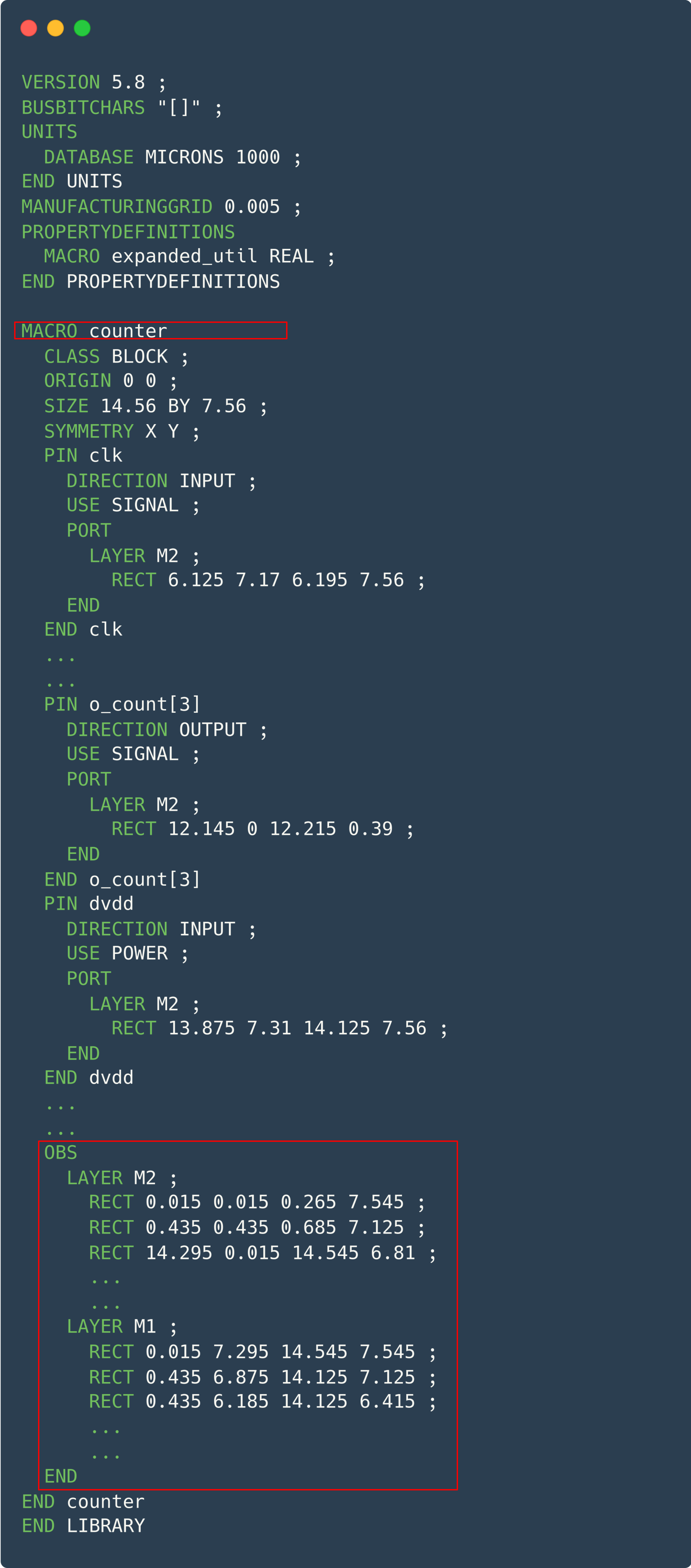 Example of a Design LEF file
OBS
    LAYER layerName
    RECT xy xy ;
END
The OBS statement defines a set of obstructions (also called blockages) in the macro. Obstructions normally prevent routing, except when a pin overlaps an obstruction (the port geometry overlaps the obstruction). For example, you can define a large rectangle as a met1 obstruction and have a met1 port in the middle of it. The port can still be reached by a via, as long as the via is completely inside the port.
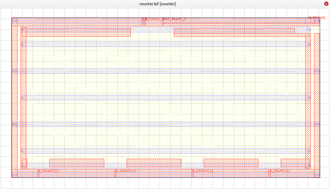 Example of the abstract view of a design
Digital flow steps that use the LEF file
The .lef file is used mainly in the place and route (PnR) step during physical synthesis in the digital flow. In this phase the abstract layout of the circuit is created, including the placement of the components, the routing of the interconnections and the definition of the metal layers and vias.
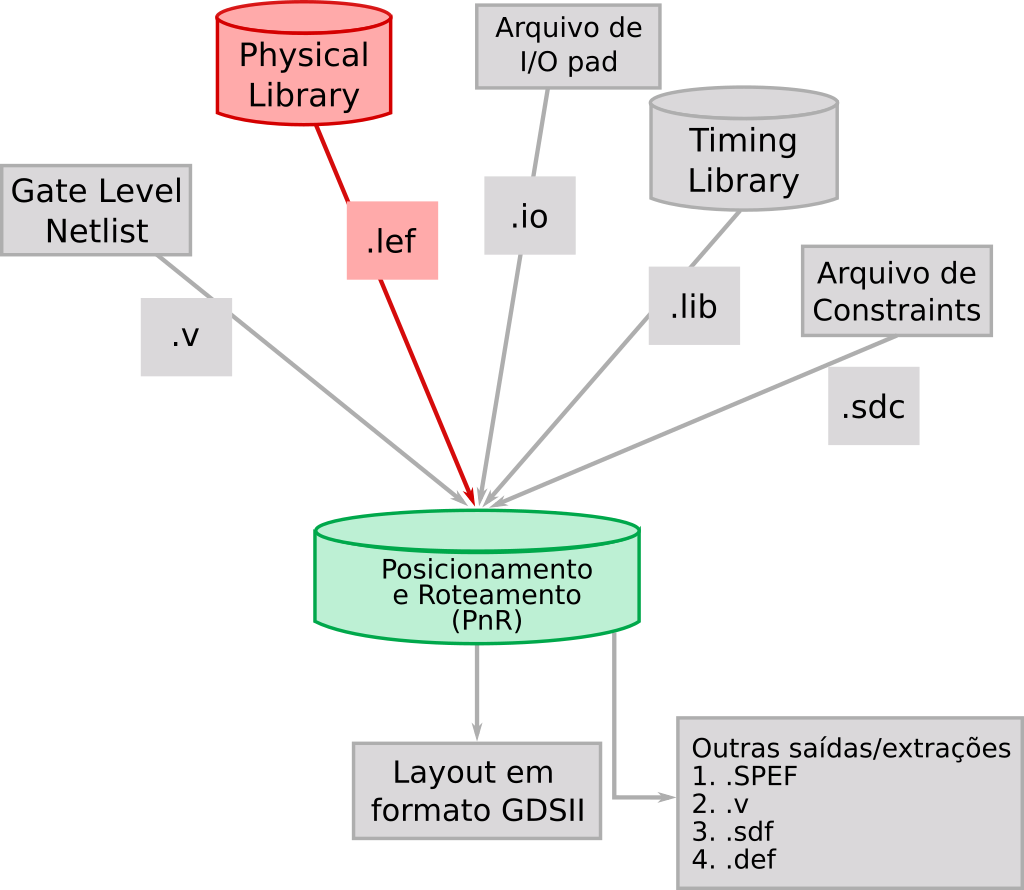 Diagram of the digital flow step that uses LEF files
The .lef file contains essential information about the dimensions and physical characteristics of the components, as well as details on the metal layers, vias, spacing rules, track widths and other information relevant to the physical implementation of the circuit. So the .lef file guides the physical design tool as it generates the final layout of the circuit.
Video
References
https://www.ispd.cc/contests/18/lefdefref.pdf. Accessed on 24-Jul-2023
http://coriolis.lip6.fr/doc/lefdef/lefdefref/LEFSyntax.html.. Accessed on 24-Jul-2023